What Is Metal Fabrication and How Does It Work?
Metal fabrication is the practical craft of turning sheet, plate, tube, and structural sections into useful products. It connects design drawings with physical objects, from stainless-steel enclosures to welded bridge components. In a typical workshop, technicians measure material, cut it with lasers or saws, form it with presses, and join parts through welding, riveting, or bolting. The finished surface may then receive grinding, painting, galvanizing, or powder coating.
The scale of this work is substantial. The World Steel Association reported approximately 1.89 billion tonnes of crude steel production worldwide in 2023. Much of that material must be processed before it becomes equipment, buildings, transport systems, or industrial machinery. The International Energy Agency also identifies steelmaking as a major industrial source of carbon emissions, representing roughly 7–9% of global energy-related emissions. These figures explain why efficient metal fabrication matters. Better nesting can reduce scrap. Accurate cutting can prevent rework. Careful welding can protect both strength and service life.
Small details matter.
This guide explains how metal fabrication works, from material selection and digital drawings to inspection and finishing. It also considers tolerances, heat distortion, corrosion resistance, and production cost. Industry reports often present smooth growth forecasts, but workshop conditions are rarely perfect. Material defects, rushed measurements, and unclear specifications still cause avoidable problems. Experienced fabricators manage these risks through documented procedures, calibrated tools, qualified welders, and inspection records. The methods may look straightforward, yet reliable results depend on disciplined decisions at every stage.
Define Metal Fabrication Through Cutting, Forming, Joining, and Finishing
What Is Metal Fabrication and How Does It Work?
Metal fabrication is the practical process of turning raw sheet, plate, tube, or bar into a useful structure. It usually follows four connected stages: cutting, forming, joining, and finishing. Each stage affects the next. A small cutting error can create larger problems during assembly.
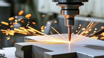
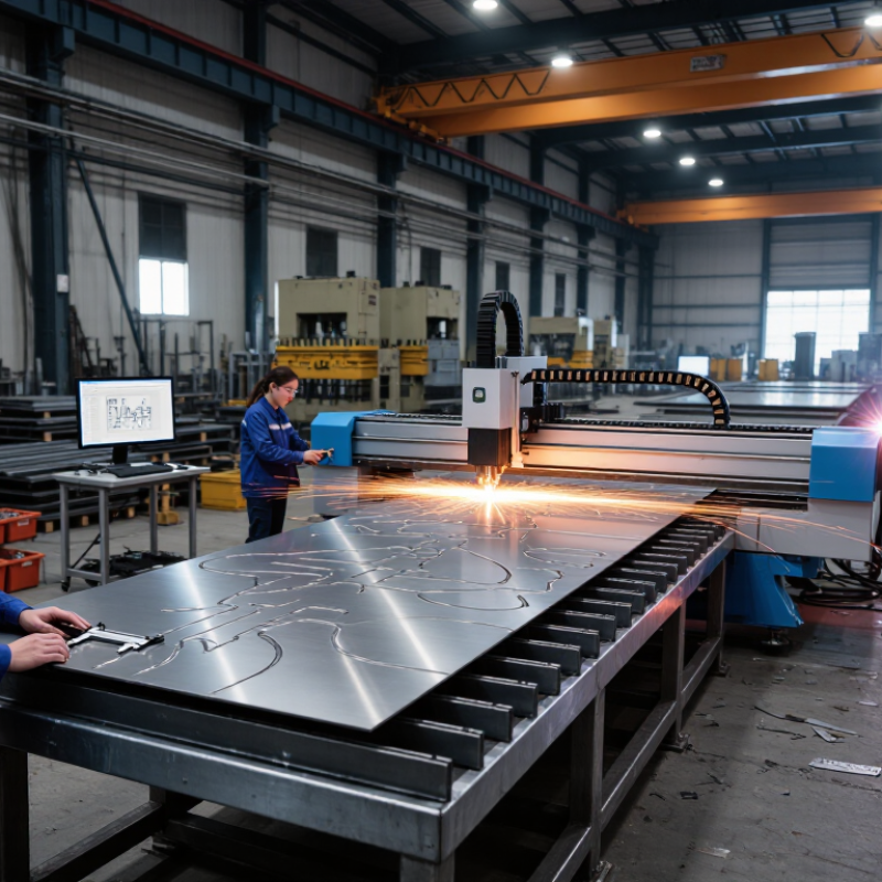
Cutting removes unwanted material with tools such as saws, shears, punches, or controlled thermal equipment. Skilled fabricators check dimensions, edge quality, and burrs before continuing. The cut may look accurate, yet heat can slightly distort thin steel. That detail is easy to miss.
Forming then changes the metal’s shape through bending, rolling, stamping, or pressing. Operators consider thickness, grain direction, bend allowance, and springback. A drawing is useful, but the real piece may respond differently.
Joining connects separate parts into one assembly. Welding is common, while bolting, riveting, and brazing suit other designs. Clean surfaces and correct joint preparation strongly influence strength. Poor alignment can remain hidden until stress appears.
Finishing improves appearance, durability, and handling. It may include grinding, deburring, blasting, coating, or polishing. Finishing is not merely cosmetic; it can reduce corrosion and remove sharp edges.
Experienced teams measure parts throughout production, not only at the end. Even careful work sometimes needs adjustment, because metal remembers force, heat, and pressure in inconvenient ways.
Select Metals by Strength, Melting Point, and Alloy Standards
What Is Metal Fabrication and How Does It Work?
Metal fabrication turns raw stock into usable parts through cutting, forming, joining, and finishing. Material choice controls nearly every later decision. Strength matters when a frame carries weight, resists impact, or faces repeated vibration. Tensile strength shows how much pulling force metal can withstand before failure. Yield strength matters earlier. It marks permanent deformation. A strong-looking part can still bend under service loads.
Melting point guides welding, casting, and heat treatment. It also affects energy use and distortion risk. Metals with lower melting points may require gentler heat control. High-temperature alloys demand suitable equipment, shielding, and skilled inspection. Yet melting point alone is not enough. Thermal expansion can shift dimensions during welding, especially in thin panels. A small heat difference may leave a visible gap after cooling. That detail is easy to miss.
Alloy standards provide a reliable language for purchasing and inspection. A standard identifies chemistry, mechanical properties, heat treatment, and permitted tolerances. Engineers should verify the material certificate, thickness, temper, and test method. Two sheets with similar names may perform differently. This is where specifications need careful review. Select metals by the finished part’s loads, temperature, corrosion exposure, and fabrication method. Then confirm the choice through testing or qualified engineering judgment. No chart replaces real service conditions.
Join Fabricated Parts Using MIG, TIG, or Arc Welding Processes
Metal fabrication turns sheet, tube, and plate into working assemblies. Welding joins these parts by creating a controlled molten pool. The joint then cools into a permanent connection. According to the U.S. Bureau of Labor Statistics Occupational Outlook Handbook (2024), welders, cutters, solderers, and brazers may see about 42,600 openings annually from 2023 to 2033. The demand is real. However, workforce demand does not make every welding process suitable.
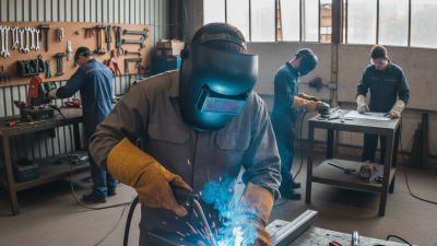
MIG welding uses a continuously fed wire and shielding gas. It suits production work because operators can create long, consistent beads quickly. TIG welding uses a separate tungsten electrode and offers tighter control. It works well on stainless steel, aluminum, and thin sections where appearance matters. A three-millimeter tube can punish careless heat input. Distortion appears fast. Arc welding, commonly using a coated electrode, remains practical for thicker steel and outdoor repairs. Its equipment is portable, but slag removal adds labor.
Professional results depend on more than bead appearance. Fit-up, joint design, cleanliness, shielding, and heat control all matter. ISO 3834 quality requirements emphasize qualified procedures, competent personnel, and inspection records for fusion-welded structures. The American Welding Society’s welding workforce studies also warn of a growing skills gap, which can affect consistency and inspection quality. A smooth bead can still hide incomplete fusion. That is an uncomfortable lesson. Fabricators should verify penetration, dimensions, and distortion before release, not after a failed assembly.
Finish and Inspect Components to 60–120 μm Coating and ISO Tolerances
Metal fabrication turns sheet, plate, tube, or bar into controlled components through cutting, forming, welding, and machining. The work is not finished when the shape looks correct. Surface preparation and inspection determine whether the part performs reliably in service.
A coating thickness of 60–120 μm requires disciplined preparation.
Oil, scale, sharp edges, and welding spatter can reduce adhesion or create thin spots. Operators usually clean, deburr, and profile the surface before applying the coating. Dry-film thickness gauges then measure several points, including edges, corners, and recessed areas.
The surface tells the story. A single reading proves little.
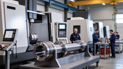
Dimensional inspection follows the approved drawing and its stated ISO tolerances. Calipers, micrometers, height gauges, and coordinate equipment may confirm hole positions, flatness, and overall dimensions. Instruments need current calibration records.
Inspectors should also verify coating thickness after final handling, because contact marks can expose metal or compress soft finishes.
Small errors matter.
A coating may look even under bright light but vary across a welded frame. That assumption deserves a second check.
Traceable inspection records should link measurements to the part, drawing revision, operator, and equipment used. If a result falls outside tolerance, rework should not begin blindly.
The cause may be uneven preparation, distortion from heat, or an unsuitable measurement location. Careful review protects both the component and the person relying on it.